Following on from his previous article about the Haoge mini ball head and the design problem with that head, René Lesseux has sent me a follow-up article on how to fix it. This article details how to add a safety pin to the ball head, so that when it is used at an angle there is no longer a danger of the head separating.
If you have previously purchased one of these Haoge branded mini ball heads, or you have a similar design ball head that lacks a safety pin, you will hopefully find this post quite helpful. While it might seem rather complicated at first glance, if you have a stand drill, the right bits and the clamp to fix the supporting plank, the fix can be done in 15 minutes.
Principles
A safety pin prevents separation of the body from the core when the lock screw of the device is removed or unscrewed.
This safety pin is made up of cylindrical piece of metal pushed into a 3 mm diameter hole to be bored in the mini ball head's black body.
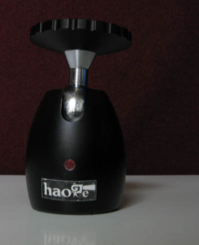
Fig 1 Fixed up mini ball head
Red wax is used here to maintain the steel pin into place (and to give an expensive Leica look).
Determining the location of the safety pin
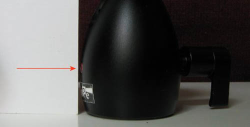
Fig 2 Location of the bore
The bore must be situated a little bit above the protuding part of the belly of the body. But to determine the exact location it is best to start by understanding the way the safety pin will operate.
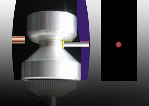
Fig 3 The safety lock mechanism
The image shows the approximate location of the M8 threaded bore used by the ball lock lever (represented here in brown) and the way the safety pin (represented in gray) will operate.
The safety pin must target a 4 mm by 4 mm area, indicated by the yellow lines, so that a permanent line of contact (green line) is created between the top of the cylinder and the surface of the ring at the base of the cup holding the ball.
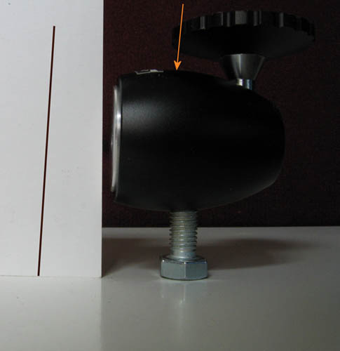
Fig 4 A slight problem
Using an M8 bolt in the bore used by the ball locking screw will greatly help us in firmly attaching the body of the mini ball head when boring our 3 mm diameter hole for the safety pin.
But as the axis of the existing bore is not perpendicular to the axis of the device we will have to find a way to compensate.
Finding the bore point
After disassembling the mini ball head, the core is placed on a flat surface and wax is pressed against it and against the supporting surface.
A sharp object is sunk into the wax pressed against the core of the mini ball. The wax is adjusted so that the tip of the sharp object points on the centre of the target area (the centre of the yellow vertical line on figure 3).
Under the ball head notch (opposite the lock screw), the body is covered with a small piece of duct tape. The wax holder is then placed against it, and the body of the mini ball rotated to scratch the duct tape.
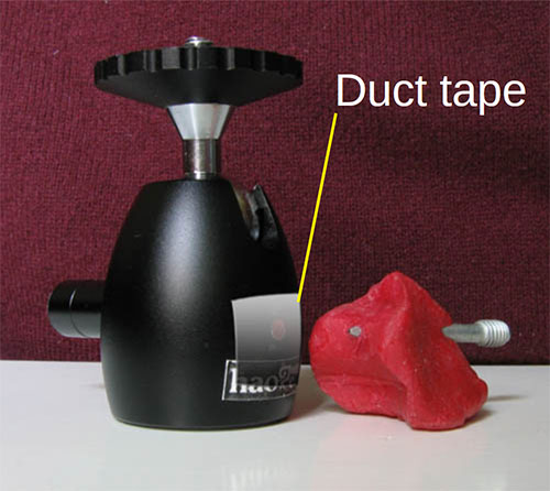
Fig 5 Finding the bore point level
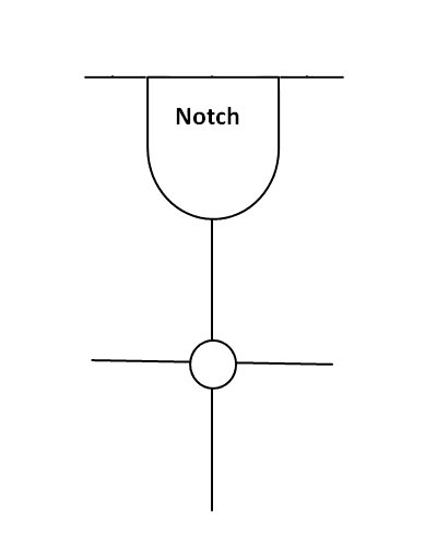
Fig 6 Marking the bore point on the duct tape
The target point is the intersection of the horizontal scratch and the vertical line passing down through the centre of the notch.
Fixing the body for boring
This is done with the help of a 2 cm thick plank which will be moved in relation to some solid object providing a reference surface. This solid object can be another piece of wood fixed to the table of the boring machine or some adjustable guide pertaining to or added to the boring machine.
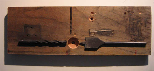
Fig 7 The ‘housing’ of the bolt
An 8 mm diameter traversing hole is bored and a slightly bigger one to accommodate the head of the M8 bolt.
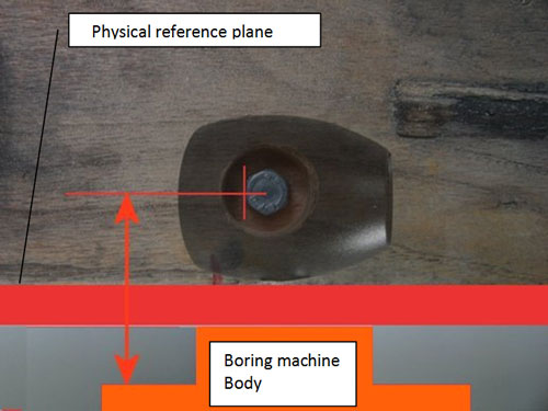
Fig 8 The mini ball body in position wth the plank leaning against the reference surface
The reference body (red) is fixed in relation to the boring machine column (orange).
The plank was placed against the reference body when boring the hole to house the bolt.
When returning the plank the 3 mm bit will attack the body at the right distance (the double arrow) but not at the right vertical angle and not at the right location.
Adjusting the bore angle
The objective is to have the boring bit perpendicular to the axis of the ball head body.
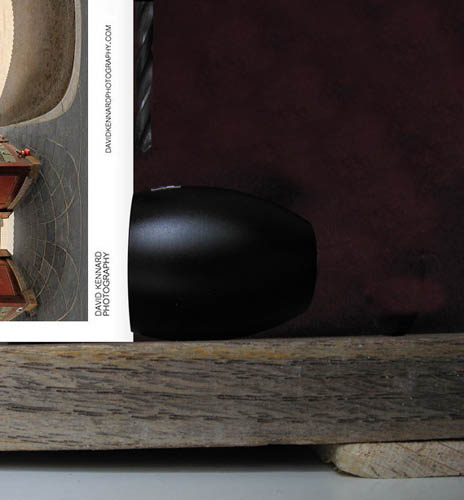
Fig 9 The tilted plank on a wood wedge
This is done by moving a wedge until the bit is parallel to the base of the mini ball body with the help of business card leant against the base of the mini ball.
When the right angle is found the support plank and the wedge are pushed against the reference plane to put the drill bit above the boring location marked on the duct tape (not shown here).
Finalizing the fix
The object used as a safety pin is any cylindrical piece of metal entering the 3 mm diameter hole. For example, a steel nail (with tip cut off), a piece of clothes hanger wire, etc.
With the mini ball head assembled, the pin is pushed into the hole until it touches the core.
The pin is marked flush to the suface of the body then extracted from the mini ball. It is then cut 1 mm shorter than the marking, so it will fit completely inside the body.
The cut to length pin is pushed back into the hole and some putty added (e.g. wax or glue) to close the hole and prevent the pin from falling out.
Leave a Reply